
Инженерная практика №05/2015
Опыт применения компоновок для одновременно-раздельной добычи ОРД-РЭК
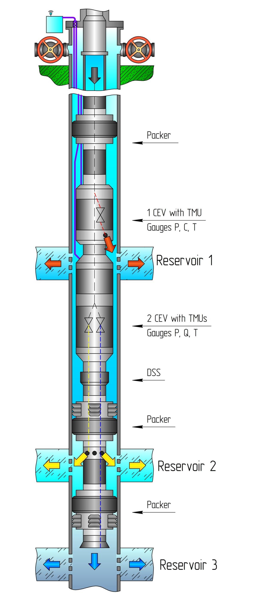
MRI-3CEV-3TMU
This patented remotely controlled completion system used in three-reservoir waterflood injection wells for reservoir pressure maintenance includes three mechanical packers with their controlled electric valves (CEV) for simultaneous multi-reservoir injection (MRI) into three reservoirs through a single tubing string. A reagent is injected through the wellhead and a single tubing string into the upper CEV and the lower TMUs for real-time measurement of pressure, flow rate and temperature (P, Q and T) and flow-rate control using CEVs separately for three reservoirs.
Applications:
- For cost reduction in multi-reservoir fields and waterflood injection wells penetrating reservoirs with different properties;
- To use currently inactive wells and reservoirs for reservoir pressure maintenance;
- To shut in a reservoir in an injection well for maintenance and workover operations in responding production wells with no well killing
Benefits:
- The entire system, including controlled electric valves (CEV), is controlled in real time remotely or from Geonik‘s control station;
- Two-way communication to obtain injection data from telemetry units (TMU) with Р, C and T gauges and precise opening and closing regulation of CEVs through logging cable;
- Dynamic testing of each reservoir with recording of pressure fall-off curves by shutting in one of the reservoirs;
- The system is run and set in the well in two stages: (1) setting a two-packer system and (2) running an SIMU and the upper packer on tubing for connection to the two-packer system;
- Real-time injection management of each reservoir using downhole gauge and flow-meter data from TMUs;
- Lower TMU with the upper packer can be retrieved from the well without the lower two-packer system;
- No additional tubing used with hydraulic valves for multi-reservoir injection is required due to ease of installation and high performance of the system.
| Item code | Casing string, mm/inn | CEV seat diameter mm/in | Pressure difference at CEV, MPa/psi | Maximum temperature (°C/F)
TMU w/gauges |
Tubing thread diameter mm/inn | Downhole environment | |
| Nominal diameter | Wall thickness | ||||||
| MRI-3CEV-3TMU-118 | 140/5.51 | 6-8/0.2-0.3 | 12/0.47; 20/0.78 ⃰ | 30/
4351 |
120/248; 150/302 ⃰ | 73/2.87 | Formation water
Oil Associated gas Gas condensate Natural gas |
| 146/5.74 | 9-11/0.35-0.43 | ||||||
| MRI-3CEV-3TMU-120 | 146/5.74 | 6,5-10/
0.23-0.39 |
12/0.47; 20/0.78 ⃰ | 30/
4351 |
120/248; 150/302 ⃰ | 73/2.87 | |
| MRI-3CEV-3TMU-140 | 168/6.61 | 8-11/
0.3-0.43 |
12/0.47; 20/0.78 ⃰ | 30/
4351 |
120/248; 150/302 ⃰ | 73/2.87 | |
| 178/7 | 13-15/
0.51-0.59 |
||||||
| MRI-3CEV-3TMU-145 | 168/6.61 | 7,3-8/
0.27-0.31 |
12/0.47; 20/0.78 ⃰ | 30/
4351 |
120/248; 150/302 ⃰ | 73/2.87 | |
| 178 | 11.5–12.7 | ||||||
* by personal request